We develop optimal approaches to mathematical modeling of products
The air supply to the deflector can be carried out both straight-line (Fig.1) and sideways (Fig.2).

Fig. 1 Example of a CAD model for calculation software

Fig. 2 Example of a CAD model for calculation software
Flow Engineering engineers use a modern software package for computational gas dynamics ANSYS CFX. ANSYS CFX combines advanced solver technology with a modern user interface and adaptive architecture, which makes this tool available both for developers with general engineering knowledge and for specialists in the field of hydrodynamics working with the model and its properties at a deep level.
CFX allows you to study equipment and processes in detail from the inside, increase efficiency, increase service life and optimize processes. The heart of the ANSYS CFX module is an advanced algebraic multigrid conjugate solver using Coupled Algebraic Multigrid technology, which is the key to obtaining accurate results in a short time. The solver parameters and boundary conditions can be adjusted during the calculation, and there is no need to stop the solver.
The ANSYS CFX solver uses a second-order discretization scheme by default, ensuring that the most accurate results are obtained. The use of the ANSYS CFX coupled solver technology provides significant advantages for any calculation, no matter for rotating machines, multiphase flows, combustion or for any other physical model and allows you to obtain stable and scalable solutions for fluid dynamics problems. Most industrial flows are turbulent, so the ANSYS CFX module has always paid special attention to the development of modern turbulence models for efficient and accurate calculation of turbulent processes [1].
Finding current lines and velocity values in Flow Engineering deflectors was performed numerically in the ANSYS 2021 R2 CFX software package. To solve this problem, 1:1 ventilation duct models were exported to ANSYS and one of the most popular general RANS turbulence models, k - epsilon, was used.
With the numerical method of solving problems of gas dynamics, the computational domains must be divided into elements of finite volume. For a specific task, all calculations were performed with a characteristic cell size of 5 mm in the area of the slit diffuser. In areas simulating the volume of the room and the air supply channel, the characteristic size of the cells is 60 and 10 mm, respectively. The total number of cells with this division is in the range from 3 to 3.5 million, depending on the configuration of the deflector. These characteristic dimensions and the total number of cells allow us to obtain a result that is in good agreement with the experiment.
To obtain experimental data, a modern method of optical diagnostics of 2D PIV flows with good spatial and temporal resolution was used. The main initial condition in the problem is the mass expenditure rate, which is generally accepted in a wide range of values.
When modeling the air flow in the ventilation ducts of the initial configuration, a number of gas-dynamic problems were identified, such as the unevenness of the velocity field at the outlet of the slit diffuser and the scattering of current lines. When air enters the ventilation duct from the channel through the diffuser, a strong vortex formation occurs, and the distribution plate does not compensate for this in any way. The air flow lines at the outlet of the slit diffuser with rectilinear and lateral supply break up into disordered bundles (Fig. 3,5) and randomly diverge along the volume simulating the room. The velocity profile at the outlet of the slit diffuser is uneven (Fig.4,6), which in turn does not meet any climatic standards of office or residential premises.

Fig. 3 Air flow lines in the ventilation air distribution device

Fig. 4 Distribution of velocity values in the output section of the slit diffuser with a rectilinear supply of the working mass

Fig. 5 Air flow lines in the ventilation system with lateral supply of the working mass

Fig. 6 Distribution of velocity values in the output section of the slit diffuser with lateral supply of the working mass
To eliminate the problems described above and, accordingly, to implement high-quality and efficient ventilation of premises, the geometry of the structure should be transformed so that the air flow lines at the outlet are ordered and directed along the flow, and the velocity profile is close to uniform. To achieve this task, different geometric configurations of the deflector were calculated and the following design amendments were determined: it is recommended to extend the slit diffuser and the distribution plate for the entire length of the ventilation duct, it is recommended to install a honeycomb in front of the slit diffuser for the laminarization of the output air flow.
These corrections make it possible to significantly reduce the dispersion of the current lines (Fig.7) and the unevenness of the values of the air velocity at the outlet (Fig.8). Obviously, some unevenness still remains, but it can be negated by varying the height and length of the honeycomb rib.

Fig. 7 Current lines in the upgraded ventilation device

Fig. 7 Current lines in the upgraded ventilation device
Determination of flow values by characteristic sections of the flow part and formation of a table of product parameters.

Fig. 9 Determination of characteristic cross sections in the flow part of the simulated device
In Figure 9, the figures show the main sections, 1 – the initial section of the supply air channel, 2 – the area of the junction of the air channel and the static pressure chamber (SPC), 3 – the initial section of the air distribution linear grid, 4 – the output section of the air distribution grid. In characteristic sections, the flow parameters are determined by means of various averaging, for example, averaging over the geometry of the Area Average or averaging the parameters over the air flow Mass Flow Average.

Fig. 10 Distribution of characteristic cross-sections for determining the range parameters of a submerged air jet
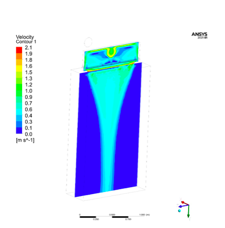
Fig. 11 One of the longitudinal sections of the distribution of velocity parameters in the case of ultra-low air flow through the product