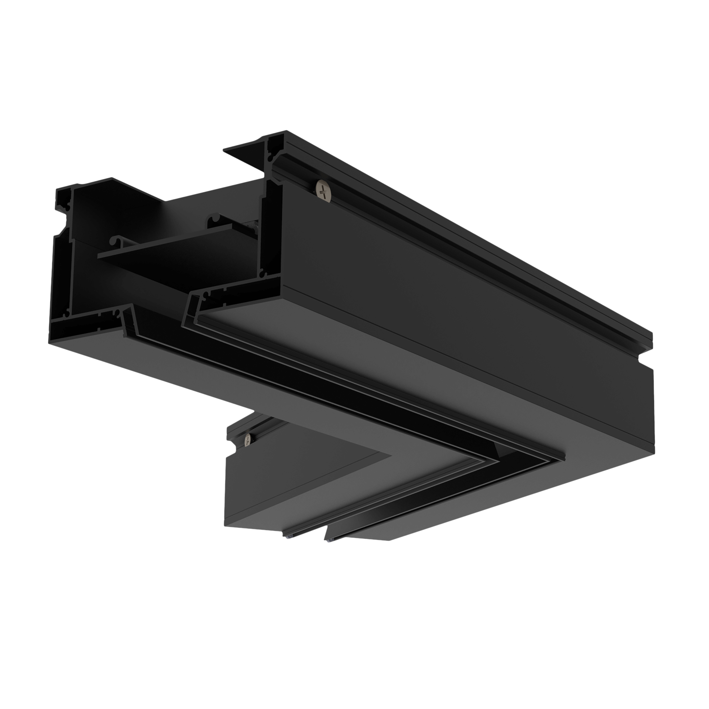
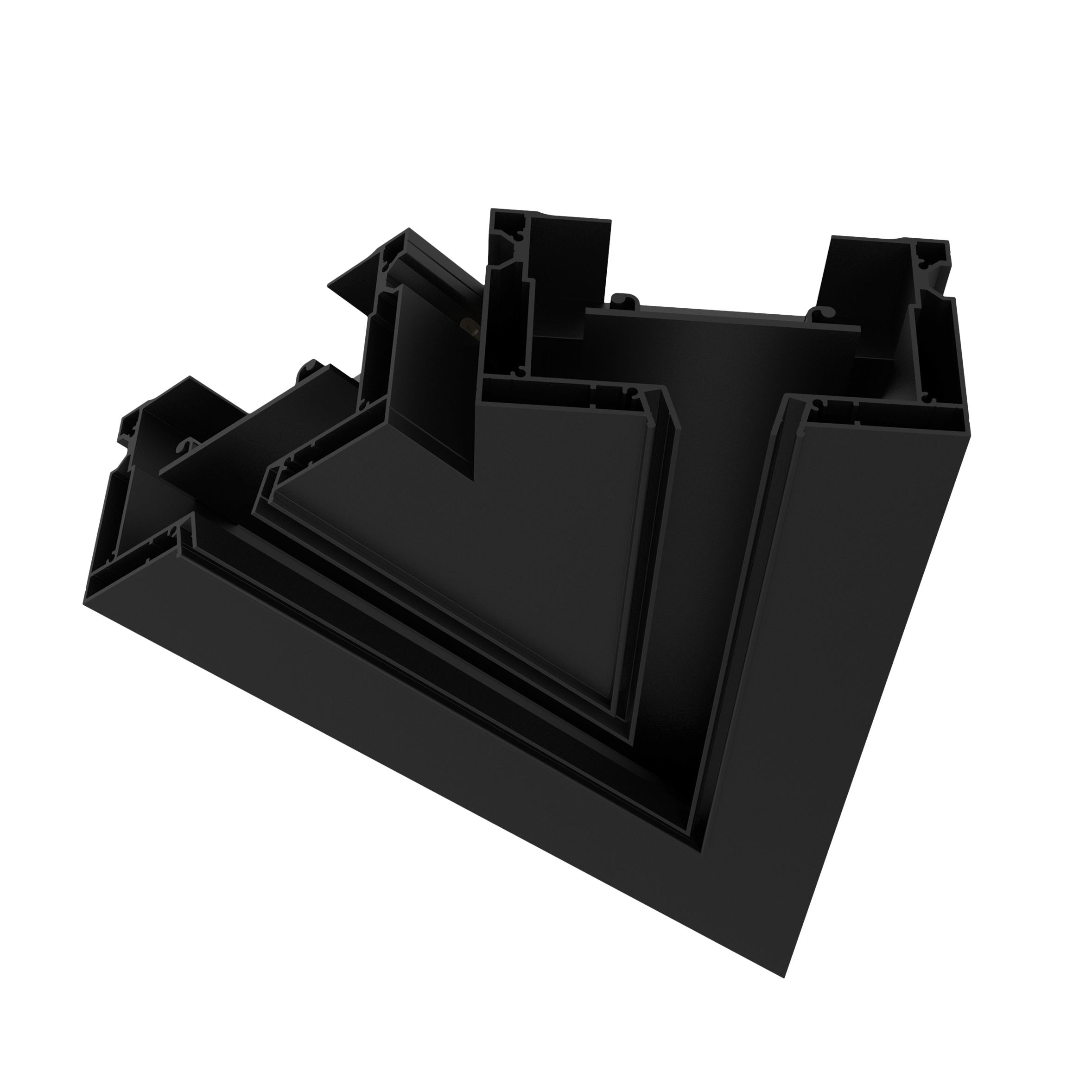
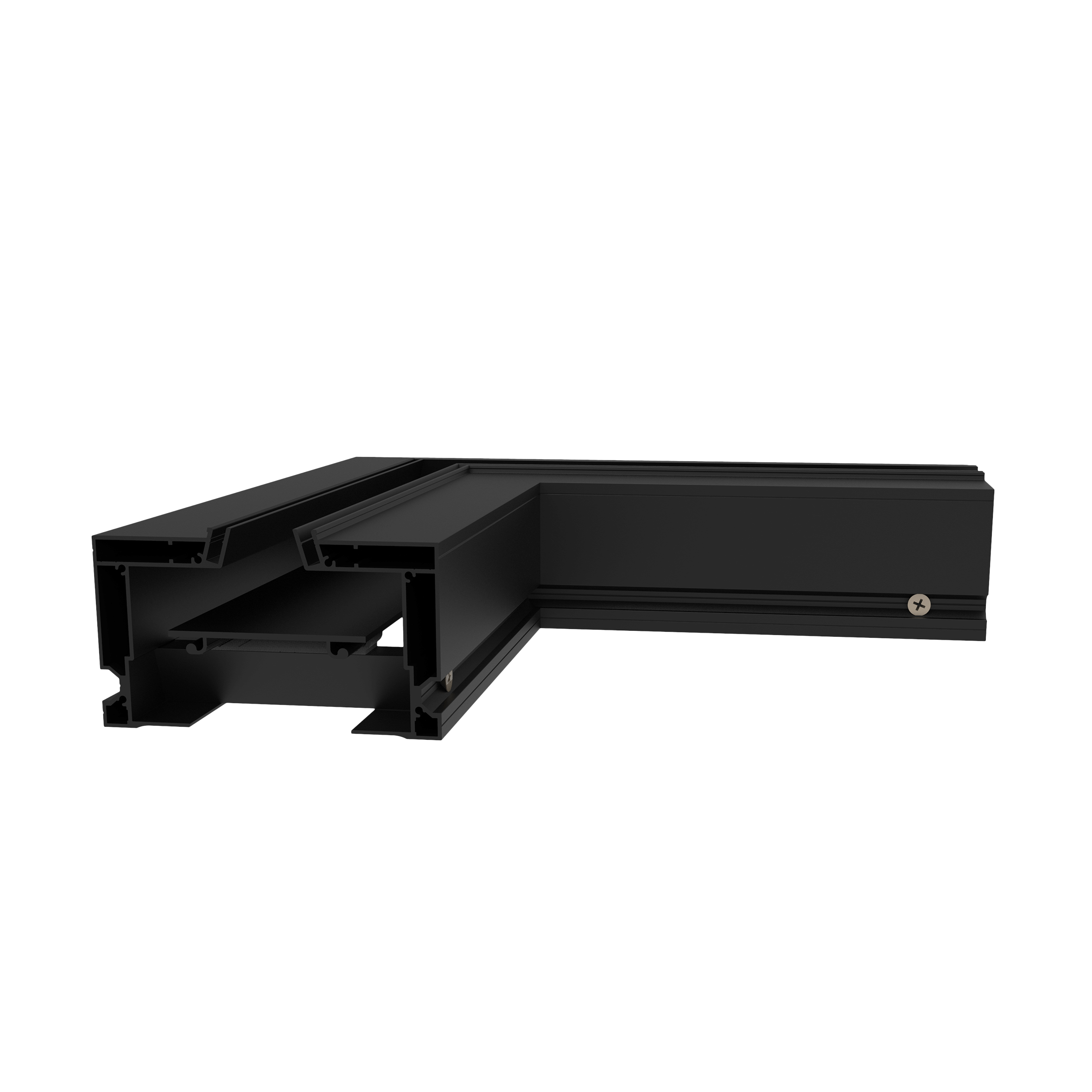
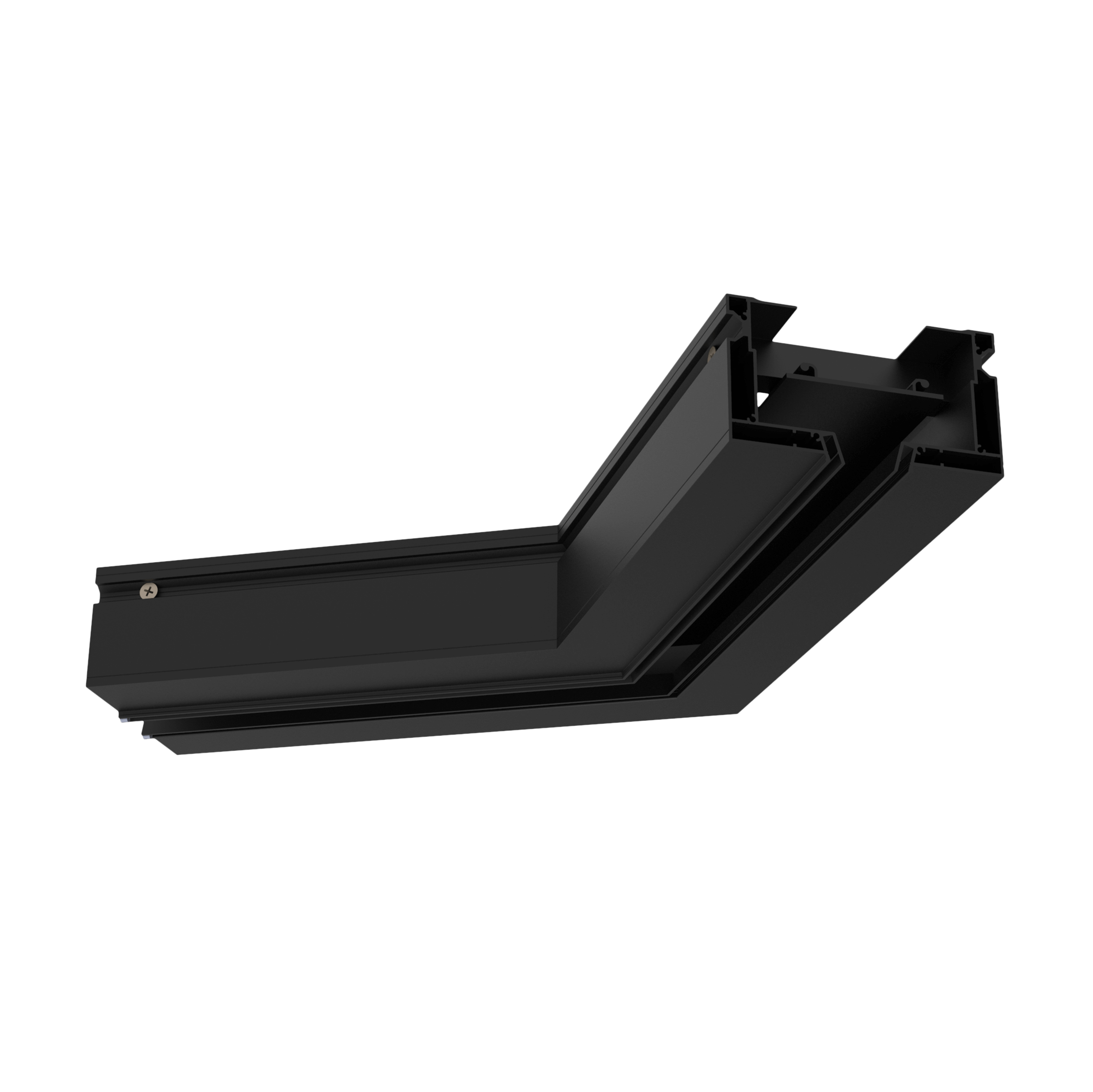
Corner element for fabric stretch ceiling (Model A)
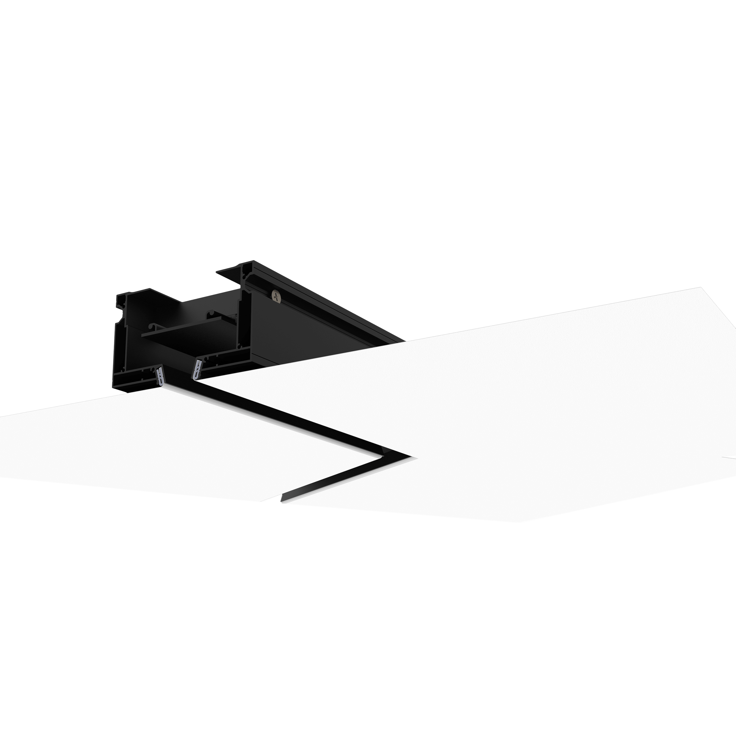
The angular element of the system is designed for the supply and removal of air in rooms for various purposes. The unit belongs to flush-mounted ventilation systems. The standard nomenclature of angles is 45/90/120 degrees. It is possible to manufacture any configuration of the architectural line taking into account non-standard ceiling and wall solutions. It has a profile wedge-shaped fastening system for fabric fabric, which greatly simplifies installation.
Perfect coupling of the elements, thanks to the damper assembly and special connectors. Provides uniform tension.
It has various coating options:
- Powder coating in the RAL palette
- Non-ferrous metals: brass, bronze, copper, gold, silver, chrome.
- Carbon coating.
- Decorative veneer finish of valuable wood species.
Product information

Main parameters and characteristics of the model:


A. Table segments corresponding to a constant value of the sound power level.
B. CFD (Computational Fluid Dynamic) design scheme of the Flow Engineering ventilation system, the characteristic cross sections of the main aerodynamic structural elements are indicated by numbers:
1 - the initial section of the supply air ventilation pipe (length 1 m),
2 - the inlet section of the static pressure chamber (SPC) of standard design,
3 - input cross-section of the linear lattice,
4 - output section.
As the initial conditions for the calculation, the supply air flow rate Gv [m3/h] was set in a wide range of 50-450 [m3/h], the table value of the velocity reflects the average output value at the outlet of the grid <V> [m/s], the calculations are implemented with an initial turbulence of 5%, constant temperature of 20 degrees Celsius and constant air density of 1.18 kg/m3, turbulence model k-epsilon.
C. The total pressure loss is defined as the difference of the averaged values in sections 2 - 3 (total pressure loss in the SPC) and 3-4 (total pressure loss in the diffuser).
D. The range characteristics reflect the average speed values at different distances from the plane of the output edge of the linear diffuser.

General graph of pressure losses in the diffuser:
General graph of pressure losses in the SPC:
Installation scheme

Model BIM
БИМ модели
Quality certificates
Сертификаты качества
Product passport
Паспорт продукта